
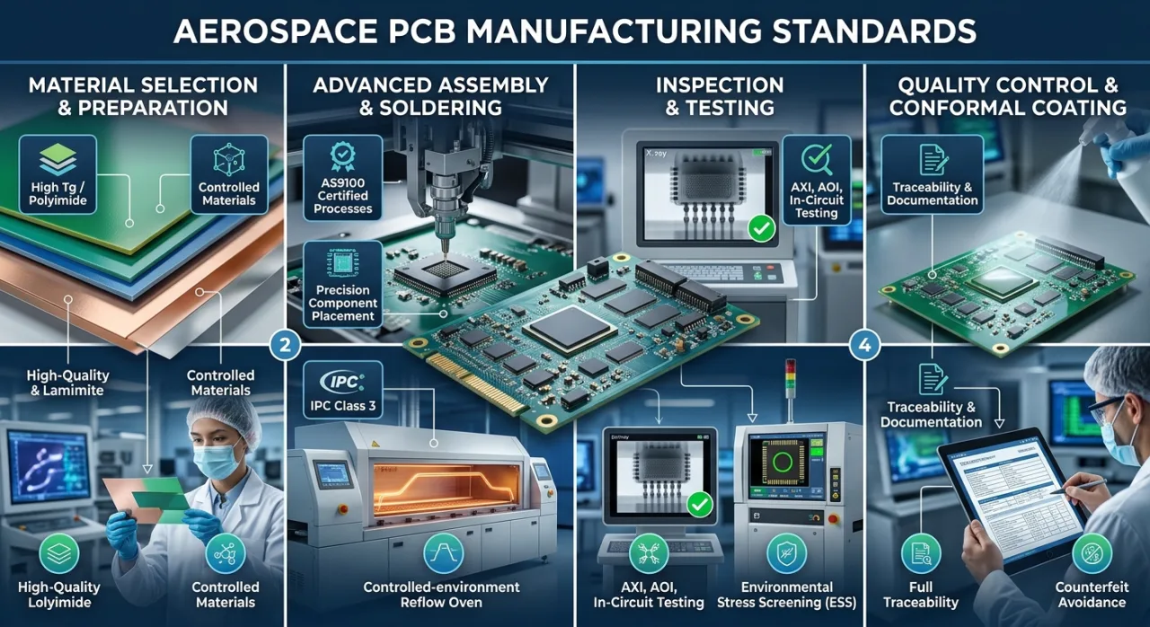
 Electronics deployed in aircraft, spacecraft, and defense systems must operate flawlessly in environments that instantly destroy ordinary consumer hardware. Extreme temperature swings, constant vibration, high-altitude radiation, and uncompromising safety mandates dictate how circuit boards for these missions are designed, fabricated, and tested.
Unlike standard commercial electronics production, aerospace manufacturing demands absolute control. Every raw material, solder joint, and test result must be thoroughly documented, verified, and traceable.
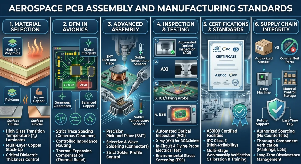
1. Critical Material Selection for High-Reliability Boards
Standard fiberglass laminates soften and expand under high thermal stress. Flight hardware requires advanced substrates engineered to maintain structural and electrical integrity across severe conditions.
-
Substrate Materials: Production teams use polyimide or high glass-transition-temperature ($T_g$) laminates. These materials remain dimensionally stable across wide thermal ranges.
-
Copper and Dielectric Selection: Designers choose copper weight, dielectric thickness, and surface finishes for optimal signal integrity and long-term solderability rather than lowest cost.
-
Thermal Management: Power-heavy sections utilize metal-core or heavy-copper constructions to dissipate heat rapidly, protecting components from degradation over thousands of operating hours.
2. Design for Manufacturing (DFM) in Avionics
A board that is difficult to assemble is impossible to inspect and repair reliably. Avionics layouts incorporate specific design principles to mitigate physical stress:
-
Generous Clearances: Layouts use wide spacing and careful fan-out patterns for fine-pitch integrated circuits.
-
Controlled Impedance: High-speed signals in communication payloads and flight computers require strict impedance routing.
-
Thermal Expansion Compensation: Repeated thermal cycling creates stress between the board, components, and enclosures. Thermal relief pads, balanced copper distribution, and strategic component placement prevent solder joint cracking.
3. Advanced Assembly and Precision Soldering
The assembly stage integrates automated surface-mount technology (SMT) with through-hole techniques for maximum mechanical resilience.
-
Precision Placement: Automated pick-and-place machines position components accurately, followed by precise reflow profiling.
-
Selective Soldering: Connectors and heavy inductors undergo wave or selective soldering to withstand high mechanical shock and vibration.
-
Strict Process Control: Solder paste printing, regular stencil cleaning, and humidity control prevent defects such as voiding, tombstoning, and insufficient wetting. Programs specify either trusted tin-lead alloys or compliant lead-free alternatives based on mission requirements.
4. Comprehensive Inspection and Testing Protocols
Inspection separates high-reliability production from standard contract manufacturing. Every board undergoes a rigorous multi-stage verification pipeline:
| Inspection Method | Target Focus | Defect Detection |
| Automated Optical Inspection (AOI) | Surface-level layout | Component placement, missing parts, and incorrect polarity |
| X-Ray Inspection (AXI) | Hidden joints | Voids, bridging, and cracks under BGA and dense packages |
| In-Circuit / Flying-Probe Testing | Electrical parameters | Opens, shorts, and passive component tolerances |
| Environmental Stress Screening | Full operational simulation | Thermal cycling and vibration faults under load |
5. Core Certifications and Quality Standards
Aerospace manufacturing is strictly governed by international aerospace standards to eliminate manufacturing variance:
-
AS9100 Certification: Facilities must hold current AS9100 quality management certification tailored specifically for aviation, space, and defense sectors.
-
IPC Class 3 Compliance: Production strictly follows IPC Class 3 acceptance criteria the highest workmanship class for high-reliability electronic assemblies.
-
Traceability: Every test metric, inspection image, and material lot code is linked directly to the board’s unique serial number.
6. Supply Chain Integrity and Counterfeit Avoidance
Component obsolescence and counterfeit parts pose severe threats to mission success. Trusted manufacturers protect the supply chain through strict protocols:
-
Authorized Sources: Procurement relies exclusively on authorized distributors and direct factory channels.
-
Authentication: Incoming components undergo rigorous physical and electrical verification, checking part markings, lot codes, and factory documentation.
-
Long-Term Support: Program managers maintain obsolescence management plans and last-time-buy strategies to support systems designed for decades of service.
Conclusion
Building circuit boards for flight applications requires absolute discipline across materials, process control, and documentation. Investing in qualified materials, rigorous DFM, and exhaustive testing ensures zero field failures, delivering reliable hardware that engineers and operators trust when failure is not an option.
Leave a Reply